Ricon Tools
A straight cut should produce a consistent diameter from chuck to tailstock. Yet many machinists eventually ask, “why is my lathe cutting a taper instead of straight”? The answer may involve alignment, tool pressure, workpiece deflection, or uneven wear. In 2026, choosing the best lathe for straight cuts requires more than comparing swing, motor power, and advertised accuracy. Real performance depends on rigidity, calibration, operator technique, and maintenance.
Industry data supports this practical view. The Association for Manufacturing Technology’s U.S. Manufacturing Technology Orders report tracks continuing investment in precision equipment, including turning systems. Its market reporting shows why buyers increasingly examine productivity and accuracy together. The Gardner Business Media World Machine Tool Survey also treats machine capability, production demand, and technology adoption as connected factors. These reports do not diagnose one taper directly. They do show the pressure manufacturers face to achieve repeatable results with less waste.
Standards matter too. ISO 230-2 provides methods for evaluating positioning accuracy and repeatability in machine tools. However, a compliant machine can still cut badly after poor setup. I have seen a dial indicator move only a few thousandths of an inch while the finished shaft showed a visible taper. That small error matters. A heavy tailstock load, a dull carbide insert, or a slightly twisted bed can change the result. Sometimes, the operator is part of the problem.
This guide examines the best lathe features for straight cuts, then follows a practical fault-finding path. It compares bed rigidity, spindle condition, cross-slide geometry, tool height, and workholding. The goal is simple: measure the cause, correct the setup, and verify the cut with reliable evidence.
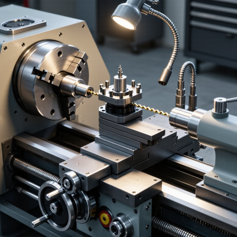
Straight cutting on a lathe means moving the tool parallel to the workpiece axis. The cutting edge should sit exactly at center height. A rigid setup helps the tool remove material evenly. Small errors matter. Secure the work firmly in the chuck, then check its runout with a dial indicator. Keep the carriage locked where appropriate, and remove chips from mating surfaces. Even the best lathe can produce a taper when setup pressure, alignment, or tool force changes.
A taper usually appears when one end measures larger than the other. Tailstock misalignment is a common cause, especially during turning between centers. Bed wear can also alter carriage travel near the headstock. A dull tool, excessive feed, or flexible stock may push the cutting edge away from the work. Measure both ends with a micrometer after a light test pass. Do not trust appearance alone. I once blamed the tailstock too quickly; the real problem was poor chuck seating.
Correct the cause in small steps. Clean the chuck jaws, verify center alignment, and inspect the tool holder for movement. If the tailstock is offset, adjust it gradually and repeat the test cut. For slender work, reduce cutting pressure and support the free end. Check diameter changes after the workpiece cools. Heat can distort measurements. A worn lathe bed may require compensation, but that solution demands careful records and repeated checks. Rushing this process often creates a second taper.
2026 Best Lathe for Straight Cuts: Why Is It Cutting a Taper?
How to Confirm a Taper in the Finished Workpiece
A finished shaft may look straight, yet a small taper can hide under oil and poor lighting. Measure two diameters with a calibrated outside micrometer. Use the same spindle angle and measuring force. Record readings near both ends, not just at the center.
For example, a 25.00 mm reading at the chuck and 24.94 mm at 100 mm away equals a 0.06 mm taper over 100 mm. Repeat each measurement three times. NIST measurement guidance commonly uses an expanded uncertainty of k=2, representing approximately 95% coverage. Therefore, a 0.01 mm difference may not be meaningful without checking instrument uncertainty and temperature. ISO 230-3 also emphasizes thermal effects during machine-tool evaluation. A cold start can mislead you.
Tips: Touch the micrometer at several angular positions. If the readings change around the diameter, suspect roundness, burrs, or deflection. Then indicate a ground test bar near the chuck and tailstock. Reverse the bar and repeat the test. A taper that changes direction may come from workholding or alignment. A consistent result can indicate tailstock offset, bed wear, tool pressure, or uneven cutting conditions. I have found that operators often blame the insert too quickly. That assumption deserves a second check. Measure tool height, reduce overhang, and make a light finishing pass before adjusting the machine. Keep the workpiece and tool near a stable workshop temperature.
A lathe can cut a taper even when the tool looks sharp and the feed feels consistent. The first check is the bed. Clean the ways carefully, then inspect for chips, burrs, or uneven wear near the chuck and tailstock. A 0.01 mm particle can distort a careful alignment check. Use a precision level only as a reference, not as proof of spindle alignment.
Check the headstock with a test bar or a ground bar held directly in the spindle. Measure near the chuck, then measure farther along the bar. A difference suggests spindle-axis error, chuck seating problems, or bar deflection. Keep the cut light. Heavy pressure can hide the real fault. ISO 230-1 emphasizes controlled measurement conditions, including thermal stability and repeatable probing. My early mistake was measuring immediately after startup.
The tailstock deserves equal attention. Bring its center to the headstock center, then test between centers with a fine finishing cut. If the diameter changes steadily, the tailstock may be offset sideways. Check vertical offset too; worn ways can make the center appear aligned while the tool cuts a taper. A 2023 Deloitte manufacturing survey reported that 86% of executives view smart operations as a major competitiveness factor. That statistic also applies to small workshops: record temperature, setup time, bar diameter, and measurement points. Guesswork is fast, but rarely reliable.
| Area to Check | Typical Taper Symptom | Practical Measurement | Typical Shop Target | Likely Cause | Corrective Action |
|---|---|---|---|---|---|
| Bed level and twist | The diameter changes gradually along the workpiece, often with the same taper repeated after tool changes. | Check the bed with a precision machinist’s level at the headstock, middle, and tailstock areas. Recheck after leveling adjustments. | The bed should remain stable and show no measurable twist change after the leveling procedure. Exact limits depend on machine length and accuracy class. | Uneven mounting pads, a distorted foundation, or excessive leveling pressure can twist the ways. | Clean the mounting points, level from the manufacturer’s recommended locations, release unnecessary foot pressure, and verify again under normal operating conditions. |
| Headstock spindle alignment | A test bar or workpiece is larger at one end even when the tailstock is not being used. | Mount a known-straight test bar or turn a short, rigid test piece. Measure both ends with a micrometer and compare the readings. | For precision work, many general-purpose lathes are checked to a few hundredths of a millimeter over a short test length, subject to the machine’s specification. | The spindle axis may not be parallel to the bed, or the headstock may have shifted after installation or impact. | Confirm the bed is correctly leveled first. Then inspect headstock mounting bolts and use the machine’s approved alignment adjustment procedure. |
| Tailstock lateral alignment | A taper appears only when the workpiece is supported by a center, and the taper direction may change after tailstock adjustment. | Use a precision test bar between centers and sweep it with a dial indicator, or compare diameters at both ends after a light finishing cut. | The centerline should be parallel to the spindle axis within the tolerance specified for the lathe; a small error can produce a visible taper over longer work. | The tailstock is offset sideways, the base is dirty, or the quill is not seated or locked consistently. | Clean the mating surfaces, align the tailstock using a test bar, lock it consistently, and verify alignment with the quill retracted and extended. |
| Tailstock height and center condition | The work may cut correctly near the chuck but show taper or rubbing near the tailstock center. | Compare the tailstock center height with the spindle center using a center-height gauge or a carefully fitted center test. Inspect center points for damage. | The centers should meet accurately without a visible vertical step, excessive pressure, or noticeable angular mismatch. | Worn center points, incorrect center fit, quill wear, or a tailstock that sits high or low can deflect the work. | Replace damaged centers, clean the tapers, check quill play, and correct height only through approved mechanical adjustments. |
| Spindle and chuck runout | The finished diameter varies between revolutions, or the apparent taper changes when the workpiece is removed and reinstalled. | Place a dial indicator on the spindle nose, a test bar, and the workholding surface. Rotate by hand and record total indicated runout. | Runout should be compared with the lathe’s service specification; precision setups commonly aim for only a few hundredths of a millimeter at the spindle or test bar. | Dirt on mating faces, a damaged chuck, worn jaws, bent tooling, or spindle bearing problems may imitate taper. | Clean all contact surfaces, inspect the chuck and jaws, test with an independent workholding method, and service bearings if runout remains excessive. |
| Tool height and tool-post rigidity | The taper changes with cutting depth, tool overhang, feed rate, or insert condition rather than with machine alignment. | Set the tool exactly on spindle center height, minimize overhang, and repeat the cut with a sharp tool and a light finishing pass. | The tool tip should be at center height and the tool post should remain firmly clamped without visible movement under load. | Tool deflection, a dull cutting edge, excessive overhang, loose clamping, or an unsuitable cutting condition can create a false taper. | Use the shortest practical tool overhang, sharpen or replace the tool, reduce cutting load, improve clamping, and use a consistent finishing pass. |
| Workpiece deflection and support | A long, slender workpiece is smaller in the middle or at the unsupported end, especially during heavier cuts. | Repeat the test with a shorter stick-out, lighter depth of cut, steady rest, follower rest, or tailstock support. | The acceptable result depends on workpiece diameter, length-to-diameter ratio, material, and cutting force; the test should be repeatable under the intended setup. | Cutting forces bend the work away from the tool, particularly with slender stock or insufficient support. | Reduce unsupported length, use a steady or follower rest, reduce depth of cut, and select a sharper tool geometry. |
| Carriage, ways, and gibs | The taper is inconsistent along the bed, changes with carriage position, or is accompanied by tight and loose spots. | Check carriage movement throughout the full travel, inspect the ways for wear, and test for side play with a dial indicator. | The carriage should move smoothly without binding, rocking, or excessive backlash while maintaining consistent tool position. | Worn ways, incorrectly adjusted gibs, chips beneath the carriage, or cross-slide play can alter tool geometry during the cut. | Clean the ways, adjust gibs according to the service procedure, remove backlash where possible, and inspect worn components. |
A lathe can produce a taper even when the setup looks correct. In my shop experience, the cutting tool is often slightly above or below center height. That small error changes the cutting force and removes more material near one end. The tool should meet the workpiece at center height, with minimal overhang. A sharp, properly ground tool also reduces pressure during a straight cut.
Workholding creates another common problem. Check that the chuck jaws grip clean, round material firmly. Uneven jaw contact can tilt the workpiece. Long stock may flex away from the tool, especially during a heavy cut. Tailstock alignment matters too. A small offset can create a visible taper across the length. I once blamed the tool, then found a damaged center hole. That mistake cost time. It also changed how I inspect setups.
A taper on a supposedly straight lathe cut usually points to setup, alignment, or workpiece deflection. I once blamed the cutting tool, but the real problem was a slightly dirty chuck jaw. Even a thin chip can hold stock off-center. Clean the jaws, face the workpiece, and check the tool height against the spindle centerline. A tool set too high or too low can rub, deflect, and change the cutting diameter.
Use a dial indicator to check the workpiece near the chuck and at the free end. Rotate the spindle by hand and watch for movement. If the reading changes, reseat the stock before adjusting anything else. Make a light test cut, then measure both ends with a micrometer. If the free end is smaller, reduce cutting pressure, shorten the unsupported length, or use a steady rest. Check tailstock alignment with a suitable test bar. Small adjustments matter. Move it carefully, then repeat the cut.
Tips: Keep the tool sharp and the feed steady. Avoid forcing a deep pass on flexible stock. Record each adjustment, because memory is unreliable. If taper remains, inspect bed alignment and tailstock offset again. I sometimes skip this final check, and that mistake costs more time than the measurement takes. A clean setup is not glamorous, but it is usually decisive.
Straight cutting moves the tool parallel to the workpiece axis. Keep the cutting edge at center height. Rigid setups help.
Taper can result from tailstock misalignment, bed wear, tool pressure, or flexible stock. Poor chuck seating can also cause it. Small setup errors matter.
Measure both ends with a calibrated outside micrometer. Use the same measuring force and spindle angle. Record readings near each end.
A 25.00 mm reading at the chuck and 24.94 mm reading 100 mm away show a 0.06 mm taper. Repeat each measurement three times.
Not always. Instrument uncertainty and temperature may affect such a small difference. Check again after the workpiece cools.
Clean the chuck jaws and mating surfaces. Check chuck seating, center alignment, tool-holder movement, and tool height. I once blamed the tailstock too quickly.
Reduce cutting pressure and tool overhang. Support the free end when possible. Use a light finishing pass. Do not rush.
Indicate a ground test bar near both ends. Reverse the bar and repeat the check. A changing taper direction may indicate workholding or alignment issues.
Operators often blame the cutting insert first. Check runout, tool sharpness, feed, and chuck seating instead. Appearance alone is unreliable.
A lathe designed for straight cuts can still produce a taper when the workpiece, machine geometry, or cutting setup is not properly aligned. This guide explains how straight turning should work and how to confirm taper by measuring the diameter at multiple points along the finished part. Comparing these measurements helps distinguish a true taper from surface roughness, deflection, or an inaccurate measuring method. If you are asking, “why is my lathe cutting a taper instead of straight,” the answer may involve bed twist, headstock alignment, tailstock offset, worn ways, or an improperly secured workpiece.
The article also examines tool height, tool sharpness, overhang, workholding pressure, and cutting forces that can bend the material or shift the tool during machining. It provides step-by-step correction methods, including checking alignment, adjusting the tailstock when appropriate, leveling or stress-relieving the setup, improving support, and taking lighter finishing passes. By following these checks in a logical order, operators can identify the actual source of the taper and restore more consistent, accurate straight cuts.