Ricon Tools
Using a boring head on a drill press can produce accurate holes, but safety depends on more than careful hand control. The machine must resist cutting forces, vibration, and unexpected movement. This 2026 guide explains how to use a boring head on a drill press safely, while recognizing that drill presses are not designed like milling machines.
Experienced machinist and educator Tom Lipton often teaches a simple rule: “Secure the work before you start the machine.” That principle applies directly here. Clamp the workpiece firmly to the table. Never hold it by hand. Remove the chuck key, inspect the boring bar, and confirm that the head is tightened correctly. A loose setup can rotate suddenly and cause severe injury.
Keep the cutting tool short and use modest spindle speed. Start with a light cut. Stop immediately if the tool chatters, the table shifts, or the workpiece begins lifting. Something feels wrong? Stop.
Personal experience matters, but it can also create false confidence. A setup that worked yesterday may fail with different material, diameter, or tool extension. Check the drill press manual before adapting it for boring operations. Wear eye protection, secure loose clothing, and keep hands away from the rotating head. Do not measure, adjust, or clear chips while the spindle turns.
The safest approach is deliberately slower. It may feel inefficient. It is still better than recovering from a preventable mistake. This guide focuses on practical inspection, controlled cutting, and honest limits, helping readers make safer decisions before power reaches the spindle.
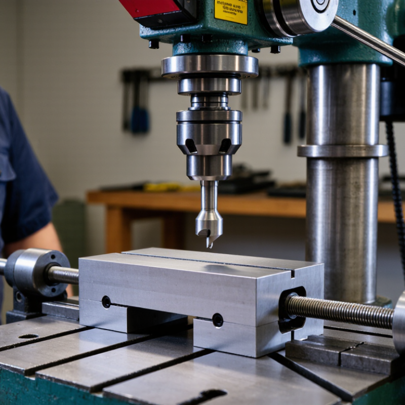
Using a boring head on a drill press requires a clear boundary between practical experience and machine capability. ISO 16090-1 provides a useful safety framework for machine-tool hazards, guarding, controls, and risk assessment. However, it does not replace the machine’s specific operating instructions. Check the manufacturer’s load rating, spindle capacity, quill travel, table rating, and permitted tooling diameter. A boring head creates radial cutting forces that can twist the quill or shift the workpiece. Keep the head close to the spindle. Secure the table firmly. Use a clamped workpiece, not hand pressure.
Numbers matter here. A 2023 U.S. Bureau of Labor Statistics report recorded about 2.6 million nonfatal workplace injuries and illnesses in private industry. That figure covers every sector, not boring-head operations. Still, it shows why general confidence is not a safety control. NIOSH recommends prioritizing engineering controls, so a rigid setup should come before speed adjustments or personal protective equipment. Start with a light cut and measure vibration, spindle movement, and table deflection. Stop immediately if the quill chatters or the head begins to wander. Small machines often lack published radial-load data. That gap needs honest judgment. A manufacturer’s maximum drilling capacity is not automatically a safe boring-head capacity, and assuming otherwise is an easy mistake.
2026 Best Safe Use of a Boring Head on a Drill Press?
A boring head can improve hole accuracy, but a drill press demands careful control. I check the spindle, arbor, and workholding before fitting the tool. The workpiece must be clamped firmly, not held by hand. A loose setup can rotate suddenly and damage the bore.
For HSS tooling, use a cutting speed between 20 and 30 m/min. Calculate spindle speed with RPM = 1,000V/(πD). Here, V is cutting speed in metres per minute, and D is the effective cutting diameter in millimetres. With V = 25 m/min and D = 50 mm, the result is about 159 RPM. I would select the nearest lower machine setting. Lower is safer.
Measure the actual boring diameter, not only the head’s outside size. Set a small radial cut, then feed smoothly without forcing the quill. Keep hands away from the rotating head. Stop the machine before measuring, adjusting, or clearing chips. A drill press is not automatically suitable for heavy side loads, so I check its rigidity and the tool maker’s limits. My first pass is often too cautious, and that is acceptable. Vibration, heat, or a changing sound means the setup needs review. Check the bore with a calibrated gauge after the spindle stops completely.
| HSS Boring-Speed Reference and Drill-Press Safety Checklist | ||||||
|---|---|---|---|---|---|---|
| Boring Diameter (mm) |
20 m/min (RPM) |
25 m/min (RPM) |
30 m/min (RPM) |
Suggested Starting Speed (RPM) |
Typical HSS Use | Safety Classification |
| 25 | 255 | 318 | 382 | 255 | Small, rigid boring operations | Lower starting load |
| 32 | 199 | 249 | 298 | 199 | Small-to-medium diameter finishing | Generally manageable |
| 40 | 159 | 199 | 239 | 159 | General-purpose HSS boring | Preferred starting range |
| 50 | 127 | 159 | 191 | 127 | Medium-diameter bores | Check machine rigidity |
| 63 | 101 | 126 | 152 | 101 | Large boring-head adjustment | Use restrained cutting depth |
| 80 | 80 | 99 | 119 | 80 | Large-diameter, low-speed boring | High torque and vibration risk |
| Calculation and Operating Limits | ||||||
| Formula | RPM = 1,000 × V ÷ (π × D), where V is cutting speed in m/min and D is the actual cutting diameter in mm. | |||||
| Example | For a 50 mm boring diameter at 25 m/min: RPM = 1,000 × 25 ÷ (3.1416 × 50) = approximately 159 RPM. | |||||
| Machine Limit | The safe operating speed is the lowest value among the calculated RPM, the drill press manufacturer's rated speed, the boring head's rated speed, and the tool holder's rated speed. | |||||
| Safe Use Checks Before Starting | ||||||
| Check | Required Condition | Reason | Action if Not Met | |||
| Workholding | Workpiece firmly clamped; never held by hand. | Boring creates radial cutting forces that can rotate or lift loose work. | Stop and improve the clamping arrangement. | |||
| Tool Assembly | Boring head, arbor, and cutter fully seated and tightened. | Poor seating can cause runout, loosening, or ejection. | Do not operate until all interfaces are secure. | |||
| Quill and Spindle | Quill locked when practical; spindle and arbor free from excessive runout. | Rigidity improves surface finish and reduces chatter. | Reduce depth of cut or use a more rigid setup. | |||
| Adjustments | Make boring-head adjustments only with the spindle stopped. | A rotating adjustment can cause entanglement or unexpected diameter changes. | Switch off, isolate power, and wait for a complete stop. | |||
| Cutting Direction | Use controlled axial feed; avoid milling-style side loading unless the machine is specifically designed for it. | Many drill presses are not designed for sustained lateral milling forces. | Use a suitable milling machine for heavy lateral cuts. | |||
| Personal Protection | Wear eye protection; keep loose clothing, gloves, and hair away from rotating parts. | Rotating tooling can catch loose items and eject chips. | Do not start without appropriate protection. | |||
| Trial Cut | Begin at the lower calculated speed and take a light test cut. | The lower speed helps reveal vibration, looseness, or excessive torque. | Stop immediately if chatter, slipping, or unusual noise occurs. | |||
| Important Notes | ||||||
| The 20–30 m/min range is a practical starting range for high-speed steel boring in common steels. Actual safe speed depends on workpiece material, cutter geometry, diameter, rigidity, depth of cut, lubrication, and machine condition. These RPM values are reference calculations, not a substitute for the equipment manufacturer's limits or a site-specific risk assessment. | ||||||
Mounting a boring head on a drill press creates rotating hazards at the spindle, cutter, and adjustable slide. OSHA 1910.212 requires effective guarding for points of operation, rotating parts, and flying chips. The guard should block accidental contact without restricting inspection or controlled adjustment.
Secure the boring head according to the machine’s instructions. Clean the taper and spindle first. Even a small chip can cause runout or loosening. Remove the chuck key before starting. Keep the spindle stopped during every setup change. A properly fitted guard should cover exposed rotating components while leaving only the necessary cutting area accessible.
Clamp the workpiece to the table with suitable fixtures, not with your hands. Support thin or irregular stock against movement. OSHA also requires fixed machinery to be securely anchored where designed for a permanent location. Check the table, column, and base before cutting. Loose hardware can turn a minor vibration into a serious ejection hazard.
A common mistake is trusting the quill lock or table friction alone. That is not reliable clamping. Test the setup by applying light hand pressure with power disconnected. The workpiece should not shift. Keep sleeves, gloves, and loose hair away from rotating parts. Chip shields and eye protection help, but they do not replace machine guarding. I would also recheck the boring head after the first few cuts; vibration can reveal a setup that looked secure.
Using a boring head on a drill press requires restraint, especially during side cutting. Confirm that the machine is rated for this operation, then clamp the workpiece firmly to the table. Never hold it by hand. Check the chuck, arbor, quill lock, and boring head for movement before starting. A drill press is not a milling machine, and excessive side load can loosen the chuck or damage the spindle.
Set the feed at approximately 0.05–0.15 mm per tooth. This value depends on material, cutter sharpness, spindle speed, and the number of cutting edges. For a single-edge cutter, feed per tooth nearly equals feed per revolution. Begin near the lower limit. Listen for chatter, watch the cut, and reduce feed if the machine vibrates. Slow and steady works better here.
Use roughing cuts around 0.5–1 mm radially, rather than removing the full allowance at once. A shallow first pass exposes poor clamping or excessive play early. Keep the boring head close to the spindle, and use the shortest practical tool projection. Measure the bore after each pass, since heat and deflection can change the result. Chips may wrap unexpectedly. Stop the spindle completely before clearing them. I still find this easy to underestimate: a quiet cut can hide a loose setup, while a small adjustment can change the bore noticeably.
A boring head can cut accurately on a drill press, but only when the setup is controlled. Before touching the tool, switch off the machine and isolate its energy source. In a covered workplace, OSHA 1910.147 requires lockout/tagout during servicing or adjustment. Apply the lock, verify isolation, and release stored energy. A loose quill or unsecured table can turn a small adjustment into a serious injury.
Check runout with a dial indicator before cutting. Rotate the spindle by hand and record movement at the boring head and cutting tool. Excessive runout may signal dirt, a damaged taper, or poor seating. Clean contact surfaces carefully. After adjustment, remove all tools from the table and keep people outside the cutting area. Perform a 10-second test run with the spindle empty. Stand to one side, not directly in line with the rotating assembly. Stop immediately if you see wobble, hear knocking, or feel unusual vibration. That pause matters.
Tips: Keep the chuck key out of the spindle before every test. Use a brush, not your fingers, to clear chips. Mark the setup position if repeated cuts are planned. I have learned that rushing this check creates false confidence. A quiet machine is not automatically a safe machine. Recheck runout after tightening, because clamping can shift the boring head slightly. Never use the test run to “see if it settles.” That is a poor experiment.
Use a cutting speed between 20 and 30 m/min for HSS tooling. Calculate RPM with 1,000V/(πD). Lower is safer.
Using 25 m/min, calculate 1,000 × 25 ÷ (π × 50). The result is about 159 RPM. Choose the nearest lower machine setting.
No. Measure the actual cutting diameter. The effective diameter controls the spindle-speed calculation. Small errors matter.
Clamp it firmly to the table with suitable fixtures. Never hold the workpiece by hand. Support thin or irregular material against movement.
Check the spindle, arbor, taper, table, column, and base. Clean the taper carefully. One small chip can cause runout or loosening.
No. Guarding helps block rotating parts and flying chips. It does not replace clamping, eye protection, or controlled adjustments. Keep sleeves, gloves, and loose hair away.
Set a small radial cut and feed smoothly. Do not force the quill. My first pass is sometimes too cautious, but caution is useful.
Stop completely before measuring, adjusting, or clearing chips. Keep hands away from the rotating head. Hands stay away.
Vibration, excess heat, changing sound, or a shifting workpiece requires inspection. Disconnect power before testing movement. Do not trust table friction alone.
Wait until the spindle stops completely. Use a calibrated gauge to check the bore. Recheck the head after early cuts, because vibration may expose a weak setup.
Using a boring head on a drill press safely begins with recognizing the machine’s limits. Check the drill press capacity, spindle load rating, quill travel, and rigidity against the manufacturer’s specifications and relevant ISO 16090-1 guidance. Calculate spindle speed with RPM = 1,000V/(πD), using an HSS cutting speed of approximately 20–30 m/min, then select a conservative setting for the tool and material. Secure the boring head correctly, clamp the workpiece firmly, and keep all guards in place in line with OSHA 1910.212 principles.
Set a moderate feed of about 0.05–0.15 mm per tooth and begin with roughing cuts between 0.5 and 1 mm, reducing these values if vibration or chatter occurs. Before cutting, inspect tool runout, tighten all adjustments, and remove loose objects from the work area. Apply lockout/tagout procedures under OSHA 1910.147 during setup or maintenance, then perform a brief 10-second test run from a safe position. These steps explain how to use a boring head on a drill press safely while minimizing tool damage, workpiece movement, and operator exposure.