Ricon Tools Ricon Tools

7 Tips for Indicating a Hole with a Boring Head?

Time:2026-10-27 Author:Sienna
0%

Accurate hole alignment begins with a stable setup, not a rushed measurement. A boring head can correct position, but it cannot compensate for careless fixturing or a dirty table. Small errors matter.

This guide explains how to indicate a hole using a boring head with practical shop-floor methods. It focuses on centering the spindle, reading the dial indicator, and checking the setup before cutting metal. You will see why clean surfaces, controlled spindle movement, and secure locks are essential. A few thousandths of an inch can change the fit of a bearing, bushing, or precision pin.

The seven tips are based on common machining practice and the mistakes that often appear during real setups. For example, an indicator may show movement because the workpiece is misaligned, not because the hole is undersized. That distinction is easy to miss. Slow down.

Experienced machinists also verify results instead of trusting one indicator sweep. Rechecking after tightening the fixture can reveal shifting that was invisible earlier. The process may feel repetitive, but repeatability is what makes the final bore dependable. These methods should be adapted to the machine, tooling, material, and required tolerance. Personal judgment still matters. Even careful operators occasionally overlook a small chip beneath the workpiece.
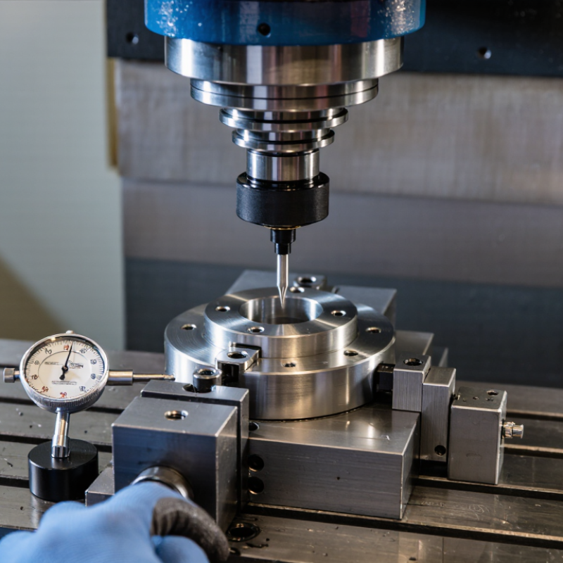
7 Tips for Indicating a Hole with a Boring Head?

Understanding Boring Head Components and Hole-Location Requirements

A boring head locates a hole through controlled radial adjustment, not guesswork. Check the body, spindle connection, slide, adjustment screw, tool holder, and locking mechanism before cutting. Each component affects accuracy. A loose slide can shift the boring bar during rotation. It happens easily.

Set the workpiece from clear datums, then mark the required hole center with a probe or layout tool. Confirm the X and Y coordinates before mounting the boring head. Measure spindle runout and keep the tool overhang short. The cutting edge should sit at the correct height and remain rigid. Adjust the slide in small, readable increments; never force the screw. Lock the mechanism gently, because excessive pressure may move the setting. Take a light test cut, stop the machine, and measure the diameter and location. Recheck the hole against the drawing’s tolerance, edge distance, depth, and intersecting features. A center can be accurate yet still fail if the hole lacks clearance. Keep the table and fixture clean. Even a thin chip can move the workpiece. I once trusted a dial reading without checking the datum, and the error became obvious only after measurement. That mistake is worth remembering. For repeat work, record the adjustment, tool projection, material, and measured result. Consistent records make the process more reliable, though they never replace inspection.

Preparing the Workpiece and Boring Head for Accurate Indication

7 Tips for Indicating a Hole with a Boring Head?

Preparing the Workpiece and Boring Head for Accurate Indication

Accurate indication begins with a clean workpiece. Remove chips, coolant residue, and burrs from the hole and clamping surfaces. Even a thin chip can tilt the part and distort the reading. Secure the workpiece firmly, but avoid excessive clamping pressure. Thin sections may deform before measurement starts.

Inspect the boring head, arbor, and indicator stem for damage. Keep the indicator contact close to the spindle axis when possible. This reduces leverage and makes small errors easier to control. Rotate the spindle slowly by hand, not under power. Record the highest and lowest readings across one full revolution. Their difference represents the observed runout. ISO 230-2 separates positioning accuracy from repeatability, so repeat the check after loosening and reclamping the part. The readings may change.

A practical shop target is often 0.01 mm or less for precision boring, but the required limit depends on the drawing and machine capability. A 2023 NIST metrology report emphasizes traceable measurement and stated uncertainty, not just a single displayed value. Therefore, verify the indicator resolution and calibration status before trusting the result. Temperature matters too. ISO 230-3 addresses thermal behavior in machine tools, and a cold spindle can shift after several minutes. Let the machine stabilize when tolerance is tight. Small details decide large outcomes.

Aligning the Boring Head with the Existing Hole or Machining Axis

When indicating a hole with a boring head, alignment controls the final accuracy. The boring head must follow the existing hole or the intended machining axis. Even a slight angular error can create uneven walls, chatter, or an incorrect diameter.

Tip 1: Clean both surfaces carefully. Chips under the workpiece can tilt the setup. I check the table, fixture, and hole entrance before positioning the boring head. Then I bring the tool close without cutting and compare its position from several directions. A dial indicator helps reveal offset and angular misalignment. Keep the spindle stopped during this inspection.

Tip 2: Use the existing hole as the reference, not the workpiece edge. Edges may be rough, cast, or inaccurately located. With the head aligned, rotate the spindle by hand and watch the indicator movement. Small movement is acceptable, but sudden variation needs investigation. I once trusted a clean-looking edge and produced a hole that measured correctly at one side only. That mistake was avoidable.

Tip 3: Confirm the machining axis before boring deeper. The quill, spindle, fixture, and workpiece should share one straight path. Take a light trial cut and measure the diameter at both ends. If the readings differ, stop and realign. Do not compensate for poor setup by forcing the boring head. Slow checks usually protect more time than rushed adjustments.

Using Edge-Finding Methods to Establish the Hole Center

7 Tips for Indicating a Hole with a Boring Head

Using edge-finding methods to establish the hole center requires patience, not force. Begin by cleaning the bore, table, and workpiece edges. Chips can shift the reading by several thousandths of an inch. Lock the boring head, then approach the first internal edge slowly with an edge finder or test indicator.

Record the machine coordinate at the left and right edges. Average both readings to establish the X-axis center. Repeat the process on the front and back edges for the Y-axis center. For a 20.000 mm bore, opposite edge readings should differ by approximately 20.000 mm. If they do not, check the edge-finder radius, spindle runout, and backlash. Small errors compound quickly.

A dial test indicator can verify the result. Sweep the bore at spindle speed, then adjust the workholding until the needle movement is minimal. NIST Technical Note 1297 separates measurement uncertainty into Type A and Type B components, reminding machinists to record repeatability and instrument limits. ASME measurement guidance also treats accuracy and repeatability as different conditions. That distinction matters here. My own weak point is rushing the second sweep. The shortcut feels harmless. It is not. Recheck after tightening the setup, because clamping pressure can move thin material.

The hole center is established by measuring opposite edges with an edge finder and averaging each pair: X center = (12.40 + 37.60) / 2 = 25.00 mm; Y center = (8.75 + 31.25) / 2 = 20.00 mm.

Checking Indication Accuracy Before Beginning the Boring Operation

7 Tips for Indicating a Hole with a Boring Head

Checking indication accuracy before boring prevents a small setup error from becoming an oversized repair. Clean the spindle taper, boring head, and workpiece surface before mounting anything. Even a thin chip can shift the reading. Secure the workpiece firmly, but avoid distorting thin walls. Set the boring head near the planned center, not at an extreme adjustment position.

Place a sensitive indicator in the hole and keep its tip square to the surface. Rotate the spindle slowly by hand through a full revolution. Watch for the high and low readings, then adjust the table or fixture in small steps. Recheck after every adjustment. Do not trust one sweep. I have seen a clean zero change after tightening a clamp. That detail is easy to miss.

Lock the machine axes only after the indicator stays steady. Check the hole at several depths if the surface may be tapered or damaged. Confirm the boring head adjustment scale against an independent measurement, such as a test bar or calibrated rule. Remove backlash by approaching each correction from the same direction. Leave the indicator mounted for one final hand rotation. If the reading still wanders, stop and inspect the setup. A rushed start usually costs more time than another careful check.

FAQS

How should I clean the workpiece before indicating a hole?

Remove chips, coolant residue, and burrs from the hole and clamping surfaces. A thin chip can tilt the part. Wipe the surfaces twice if needed.

How tightly should the workpiece be clamped?

Clamp it firmly, but avoid crushing thin walls or flexible sections. Excessive pressure can deform the part before measurement. That error is easy to miss.

How should I rotate the spindle during indication?

Rotate the spindle slowly by hand through one complete revolution. Never rely on a powered sweep for this check. Record the highest and lowest readings.

How is observed runout determined?

Subtract the lowest reading from the highest reading. The difference is the observed runout. One sweep may not tell the whole story.

Where should the indicator contact be positioned?

Keep the contact close to the spindle axis when possible. This reduces leverage and helps control small errors. Keep the tip square to the hole surface.

Why should I repeat the check after reclamping?

Loosening and reclamping can change the reading, even when the setup looks unchanged. Repeat the measurement after tightening. I have seen zero shift.

Should I check the hole at several depths?

Yes, especially when the hole may be tapered, damaged, or uneven. Compare readings near the opening and deeper inside. Depth can expose hidden variation.

When should I stop and inspect the setup?

Stop if the reading wanders, changes after clamping, or fails to settle. Check cleanliness, backlash, fixture pressure, and tool damage. A rushed start costs time.

Conclusion

This guide explains how to indicate a hole using a boring head with a focus on accuracy, preparation, and repeatable measurement. It begins by introducing the main boring head components and identifying the hole-location requirements, including the intended center, diameter, and machining axis. Before any indication work begins, the workpiece should be securely clamped, the surfaces cleaned, and the boring head inspected and mounted correctly to minimize movement or alignment errors.

The process then covers aligning the boring head with an existing hole or establishing the correct machining axis. Edge-finding methods can be used to locate the workpiece edges and calculate the hole center accurately. After positioning, the setup should be checked from multiple directions to confirm that the indicator returns consistently and that there is no unwanted runout or mechanical play. A final accuracy check before boring helps prevent offset holes, uneven cuts, and unnecessary rework, ensuring the operation starts from a reliable and properly verified position.

Sienna

Sienna

Sienna is a skilled marketing professional with a deep expertise in our company’s core products and services. With a passion for innovation and detail, she plays a pivotal role in crafting insightful blog posts that not only highlight the unique features of our offerings but also provide valuable......